Thursday, March 21, 2013

What the heck is Vinf?

The internet is a great resource for isolated students like me without access to university libraries or college classrooms. But often Google will land me on a page over my head. I often see strange and unfamiliar terms.

Years ago I found myself gnashing my teeth and crying "What the heck is Vinf?!"

Then, as now, Vinf was a common term appearing on web pages teaching orbital mechanics.

Here is a screen capture from Atomic Rockets, a popular resource for science fiction writers:

(red underlines added by me)

And here's a screen capture from a Wikipedia article on hyperbolic orbits:

(red underlines added by me)

In the Wikipedia article they use the symbol for infinity instead of inf. By now you may have guessed Vinf is short for a hyperbola's velocity at infinity.

But why would we be interested in something an infinite distance away?

A hyperbola gets closer and closer to a straight lines called asymptotes. And as an object moving along a hyperbolic orbit gets farther from the earth, it's speed gets closer and closer to Vinf. A million kilometers out, the actual speed is so close to Vinf that we might as well call it Vinf. From page 36 of my orbital mechanics coloring book:


The formula for a hyperbola's velocity can be easily remembered if you picture Vhyperbola as the hypotenuse of a right right triangle with Vescape and Vinfinity as legs:

Vescape2  +  Vinfinity2  =  Vhyperbola2


I like to talk about hyperbolas but some people don't see the point. A fellow who calls himself Rune has informed me that transfer orbits aren't hyperbolas.
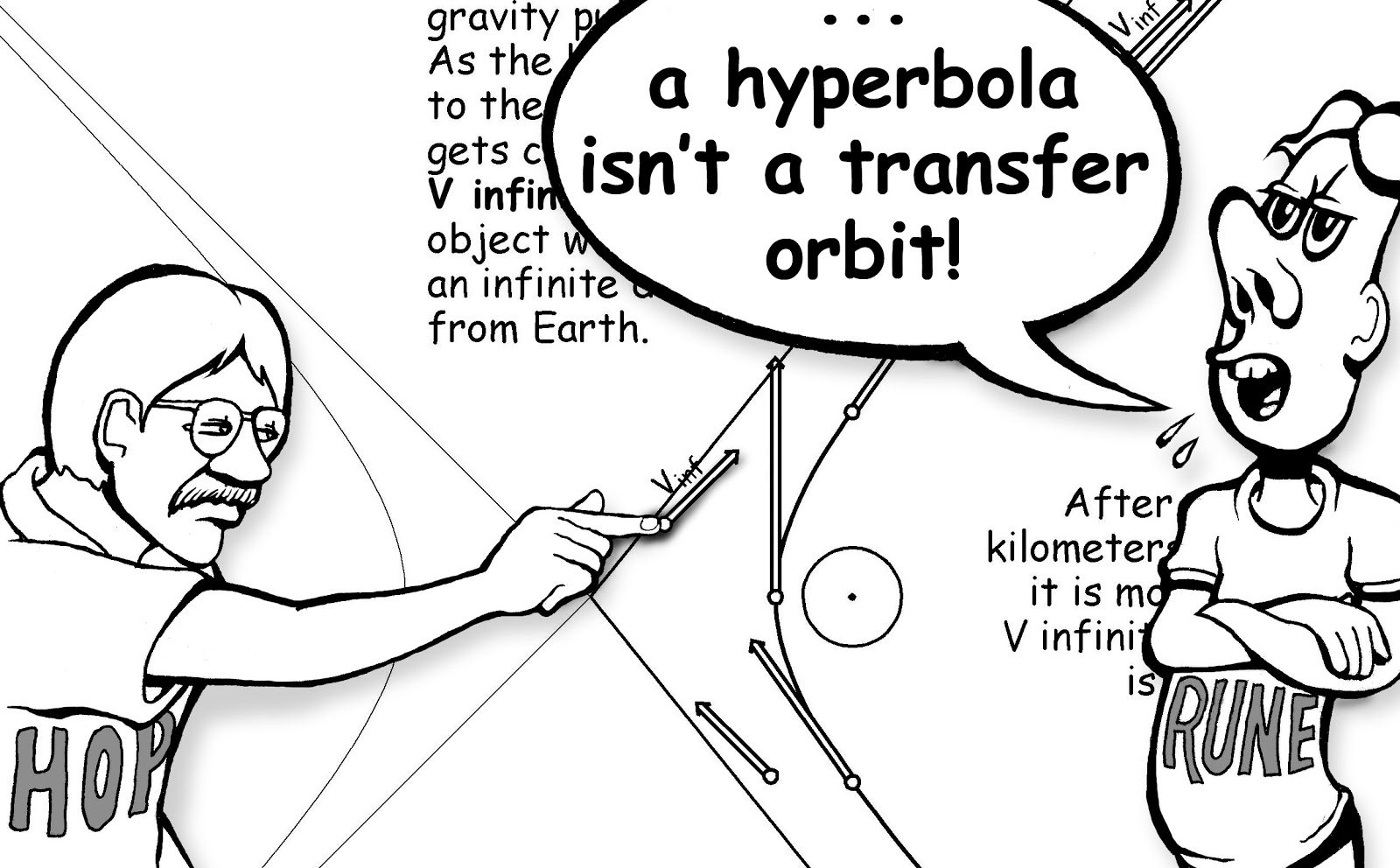


For most transfer orbits, Rune's right. A Hohmann transfer orbit from Earth to Mars is an ellipse with the sun at a focus:


Planet and asteroid orbits are also ellipses about the sun. So what's the fuss about hyperbolas?

To see let's take a closer look at our Hohmann to Mars:


At one scale we see the path as an ellipse about the sun. But magnify the Hohmann path in earth's neighborhood and we see a hyperbola about the earth.

What is the Vinf and Vesc we use to figure the velocity of this hyperbolic orbit? Let's take another look at our Hohmann ellipse about the sun:


The speed at the Hohmann perihelion (closest point to the sun) is about 33 kilometers/second. The earth is moving about 30 kilometers/second. So at perihelion, the Hohmann orbit is moving 3 km/s faster than earth. This 3 km/s is the Vinf of the hyperbolic orbit about the earth.

At the hyperbola's perigee (closest point to the earth), earth escape velocity is about 11 km/s.
So sqrt (Vescape2 + Vinfinity2) = sqrt (112 + 32) km/s = sqrt (121 + 9) km/s
Which is about 11.5 km/s.
Only .5 km/s greater than the 11 km/s earth escape velocity

And how about the Mars hyperbolic orbit?


Speed at the Hohmann ellipse aphelion (furthest point from the sun) is about 2.8 km/s slower than Mars orbit. This 2.8 km/s is the Vinf of the hyperbolic orbit about Mars.

At a low periaerion, Mars escape velocity is around 4.8 km/s.
So hyperbola speed at the Mars end of the Hohmann is
sqrt (Vescape2 + Vinfinity2) km/s = sqrt(4.82 + 2.82) km/s 
Which is about 5.5 km/s.
Only .7 km/s greater than Mars escape velocity.

Rune as well as illustrious people like Dr. Tom Murphy like to say the delta V from earth C3 = 0 to Mars C3 = 0 is around 6 km/s. Those who know how to patch conics will tell you it's closer to 1.2 km/s.

And to properly patch conics going from planet centric to heliocentric orbits we need to know Vesc and Vinf to find the velocity of planet centered hyperbolas. Since it's important, I'll repeat this:

The formula for a hyperbola's velocity can be easily remembered if you picture Vhyperbola as the hypotenuse of a right right triangle with Vescape and Vinfinity as legs:

Vescape2  +  Vinfinity2  =  Vhyperbola2


Wednesday, February 20, 2013

Golden Tethers

Φ,  also known as the golden ratio, is one of my favorite numbers. It is (sqrt(5) + 1) / 2, approximately 1.618. I've done many paintings and drawings using this number. Here are a couple:

 Two images from my coloring books

The number occurs naturally in designs having a 5 fold symmetry but it also turns up in unexpected places. I was happy to find it when I was playing with orbital tethers.

Vertical Tethers vs Space Elevators


Gravity gradient stabilized vertical tethers are smaller cousins of a full blown space elevator. Jerome Pearson has developed equations giving a space elevator's dimensions and taper ratio.

Some of Pearson's terms:

r0 planet's radius
g0 planet's surface gravity
rs radius of planet's synchronous orbit

For looking at vertical tethers I use P. K. Aravind's equations which I believe are based on Pearson's work. But I substitute the above terms with rf for r0,  gf for g0, and  rc for rs.

Tether Foot
The term rf refers to distance from planet center to tether foot. Imagine a planet the same mass of earth but with a larger radius, rf. Then rf and r0 become the same. Same with surface gravity, gravity at the tether foot would be the same as surface gravity of a planet with radius rf.

Tether Center
The term rc is the distance from planet center to radius at which a natural circular orbit would have the same angular velocity as the tether we're looking. I call this the tether center.  Misnamed since the length above the "center" is greater than the length below, but I can't think of a better word. Again, we can imagine a planet whose angular velocity is the same as our tether's, so rc would become  rs.

Tether Top
The term rt can remain the same. The tether top applies to a vertical tether just as much as it does to a space elevator. The length above the tether center must balance the length below.

Tether Size

I would like to make the tether as small as possible. Smaller size makes for less materials that have to be launched to space. A shorter length makes for greater throughput, less stress allowing less exotic tether materials and smaller taper ratios, and a smaller cross section thus reducing vulnerability to debris impacts.

The tether should be as low as possible. A lower rc makes for a higher angular velocity and a better Oberth benefit.

How low a tether foot can descend is limited by height of atmosphere. We want the foot above the atmosphere as drag would pull the tether down. So  rf is one of the first quantities considered in my tether spreadsheet.

How high to make rt? If releasing a payload from tether top sends the payload on a parabolic trajectory, we can choose any apoapsis by releasing from tether locations between rt  and rc.

Releasing a payload from a point (1+e)1/3 rc will send the payload on conic section trajectory having eccentricity e. The eccentricity of a parabola is 1. So an rt  = 21/3 rc would give us a tether able to deliver payloads to any apoapsis.

Adapting P. K. Aravind's equation (5) from his The physics of the space elevator we have

(rf / 2) * [sqrt(1 + 8(rc/rf)3) - 1] = rt

Recalling we want rt to send payloads on a parabolic path...

(rf / 2) * [sqrt(1 + 8(rc/rf)3) - 1] = 21/3 rc

Setting our units rc = 1 ...

(rf / 2) * [sqrt(1 + 8/(rf3)) - 1] = 21/3

Which comes to the suprising and pleasing result...

rt  = Φ rf

Where Φ is the golden mean, the number I was talking about at the beginning of this blog post.

The velocity of the golden tether's foot is about 68.7% the velocity of a normal circular orbit at rf .

Golden Earth Tether.
The top red orbit is a parabola.
The foot is 300 km above earth's surface. It's moving about 4.8 km/s wrt earth's equator.
Using Kevlar, taper ratio is about 5.1. Tether length is about 4130 km.

Golden Moon Tether.
The top red orbit is a parabola.
The foot is 80 km above moon's surface. It's moving about 1.13 km/s wrt moon's surface.
Using Kevlar, taper ratio is about 1.1. Tether length is about 1125 km.

The tether doesn't have to be golden. Longer tethers would be able to send payloads on hyperbolic orbits (e > 1), useful if interplanetary Hohmann transfers are desired. Shorter tethers would be limited to elliptical orbits (e < 1), but this could still be useful. This spreadsheet allows the user to set eccentricity of exit orbit as well as body's mass and radius. You can also set the altitude of tether foot.


Friday, January 18, 2013

The Dark Side of the Moon

“I'll see you on the dark side of the moon.” Folks with a little astronomy knowledge cringe when they hear these Pink Floyd lyrics. They will patiently explain there is no dark side of the moon. The moon turns a revolution over about 4 weeks. The far side as well as the near side see two weeks of darkness as well as two weeks of sunshine.

But one side is darker. Since the moon is tide locked, the far side never sees earthlight. On the other hand, someone standing on the moon’s nearside will always see earth hovering in the same region of the sky.


Viewed from the earth’s surface, both the sun and the moon subtend about half a degree. The moon’s albedo is .12, meaning it reflects about 12% of the sunlight that hits it. The moon is nearly as dark as charcoal, it only looks bright against the black void of space when our eyes have adjusted to the night’s darkness. Even the above graphic exaggerates the moon's brightness -- the sun is about 100,000 times brighter than the moon.

Viewed from the moon’s surface, the sun subtends half a degree (just as when seen from earth). But earth subtends about 2 degrees. Moreover the earth reflects about 2.5 times more light than the moon, having an albedo of around .3.


Above is a photo taken by NASA's DSCOVR satellite as the moon passed in front of the earth. The Deep Space Climate Observatory is one million miles from the earth, lieing between the earth and sun.

The larger apparent diameter and higher albedo means the earth seen from the moon is about 34 times brighter than the moon seen from earth.

The Bright Side

Let's imagine an astronaut standing at the moon's closest point to the earth. Not far from Mösting A Crater, 0 degrees latitude, 0 degree longitude. From this location, the Earth always hovers directly overhead.

Here is our astronaut pointing his iPhone straight up to snap a picture of the earth. In the foreground an iPad displays the picture he snaps:

It is sunrise. The astronaut sees a half-earth. The long shadows stretching west aren't wholly dark, they are lit by the half-earth above.

As the sun climbs towards high noon, earth is a waning crescent.
   
At noon the earth is at it's dimmest being a very thin crescent or a new-earth. But the moon remains well lit because it's high noon. Except on rare occasions when the sun passes behind the earth.

As the sun sinks towards the horizon, earth is a waxing crescent.

At sunset the waxing crescent has grown to a half-earth. The long shadows stretching east are lightened by the half-earth above.

As the sun sinks deeper behind the horizon, earth is waxing gibbous.

At midnight the astronaut sees a full-earth. This full earth is 34 times brighter than the full moon earthlings see.

From midnight to sunrise, the astronaut sees a waning gibbous earth. At sunrise we're back to where we started.

To The Dark Side

The astronaut hops in his buggy and starts driving east. As he drives closer to the far side, the earth sinks toward the horizon. When the earth is near the horizon it's possible for the sun to be below the horizon when the earth is a dim thin crescent. Even so, the astronaut enjoys strong earthlight for most the night.

When the astronaut drives over into the far side, there's no earthlight. On the far side, it's a deep stygian blackness during the two weeks from sunset to sunrise.

The far side is dark in another sense. Earth is a bright radio source. The far side of the moon is always shadowed from earth's radio noise. Radio astronomers salivate at the thought of a radio telescope under the far side's dark skies.

So you see, the Pink Floyd lyrics make some sense even if you're not under the influence.

Wednesday, January 9, 2013

Mini Solar Systems

Edit as of 6-23-2016. Many of our gas giant moons seem to have have internal liquid oceans. Liquid water  suggests regions with comfortable temperatures. These strata might also have human friendly pressures. There would certainly be lots of in situ water and organic compounds. I am becoming more interested in icey moons as potential homes for humans.

Originally I had pointed to Jupiter and Saturn suggesting similar moon systems in other star systems would make good science fiction settings. But perhaps the gas giant moons within our own system could provide such a setting. A moon need not reside within the "Goldilocks Zone" in order to accommodate humans.

__________________________


Most pulp science fiction of yesteryear relies on fast paced story lines that take place over a short time. Not plausible in our solar system where Hohmann launch windows are years apart and trip times between planets are months to years.

A setting Retro Rockets suggests is a mini solar system where trip times and time between launch windows are on the order of days instead of months or years. The "mini solar system" proposed is a gas giant with a family of moons, all orbiting in a star's habitable zone.

This is a plausible setting in my opinion. This spreadsheet shows travel between the moons of Jupiter or Saturn can occur at a good pace. The interval between launch windows is called synodic period.

The gas giants in our solar system have respectable families of moons and many are a comparable size to Mars and Mercury. Here's a graphic comparing some gas giant moons to rocky bodies in our inner solar system:


Retrorockets notes that while mini-solar systems allow a story with an exciting tempo, delta v (needed change in velocity) is still high. But a setting with much less delta V is plausible.

Many of the gas giant moons  in our solar system are tidally locked with the planet they orbit. That is, they always present the same face to the orbiting planet. From the surface of a tide-locked moon, the planet-moon L1 and L2 regions remain in the same part of the sky, much like geosynchronous satellites appear to hover motionless when viewed from the earth's surface. For tide-locked moons, L1 and L2 are possible centers for a space elevator.

Between two moons there exists an elliptical transfer orbit whose apoapsis angular velocity (ω) matches that of the upper moon and whose periapsis ω matches the angular velocity of the lower moon. If the moons are nearly co-planar, trips can be made between the moon's elevators with very little delta V. Here's an illustration showing tide-locked moons Phobos and Deimos:


Expressions for transfer ellipse's eccentricity, apoapsis, periapsis are shown above. They can be generalized to any pair of tide-locked, coplanar moons.

Transfer ellipses between Saturn moon beanstalks:


Tranfer ellipses between Galilean Moon beanstalks:


Something to watch out for is the planet-moon L1 and L2 locations. If L1 and L2 aren't well below the departure arrival point on the beanstalk, the influence of the moon's gravity might substantially alter the shape of the transfer orbit. In the case of Jupiter's and Saturn's moons, the L1 & L2s are well below the tether tops.

Another thing to watch out for is gas giant rings. The chunks of ice in Saturn's rings might well be a debris field that would quickly cut some of these beanstalks.

It is a convention to label a tide-locked moons closest point as having 0 degrees latitude and 0 degrees longitude. For a civilization evolving on a tide-locked moon, I would predict religious significance being attached to 0º, 0º point. A viewer standing at this location will see the gas giant hovering in the sky's zenith. The far and near points will gain additional military and commercial importance when they anchor beanstalks going through L1 and L2.

Our earth globe has non-arbitrary features: the north pole, south pole, equator, tropic of Cancer and Capricorn and the arctic and antarctic circles. Cartographers of tidelocked moons will have additional non-arbitrary markings: A band separating the near side from the far side. I'd also expect a circle containing the near and far points as well as the north and south poles.  A simplified globe would look like a spherical octahedron:

Here is a painting I had done of Gielo (Giant In Earth Like Orbit) and Elm (Earth Like Moon):


A very interesting setting with lots of possibilities. I hope science fiction writers will do stories of habitable moons orbiting a gas giant.

Thursday, January 3, 2013

Deboning the Porkchop Plot

Changing direction causes ΔV (change in velocity), often more than a change in speed. Compare the velocity vectors below. When going the same direction, the difference is 1 km/s. When at right angles the difference is 5 km/s. We know this from driving in traffic. Two cars going almost the same speed hit each other. If they’re in the same lane going the same direction, it’s a mild bump. If one car runs a red light and T-bones a car in cross traffic, the impact is serious: 


This is the strength of a Hohmann transfer orbit. Velocity vectors are pointing the same direction at departure as well as destination. No direction change is needed, only a speed change:


Note the Hohmann transfer path moves 180 degrees about the sun:


A Hohmann transfer assumes the departure and destination orbits are co-planar. But what if the destination orbit is inclined?

Orbit Planes and Spherical Trigonometry

A plane passing through a sphere’s center cuts the sphere along a great circle. A group of planes all sharing a common point can be represented as great circles on a sphere. Since every orbit about the sun is a conic section having the sun as a focus, each orbital plane shares the sun as a common point. Representing the orbital planes as great circles is convenient. There are already a lot of theorems in spherical trigonometry which gives us a suite of tools for looking at angles between orbital planes.

The shortest path (or geodesic) along a spherical surface between two points is an arc of a great circle. If we set the sphere’s radius to be 1, the arc length is also the angular separation in radians.

A familar group of great circles are the longitude lines on a globe. The equator is the only great circle among the latitude lines. All the longitude lines are great circles passing through the poles.

Let’s use the equatorial great circle to represent the departure plane. Recall the Hohmann transfer moves 180 degrees about the center. In this illustration, latitude and longitude for departure and destination is (0º, 0º) and (7º, 180º). The only great circle connecting these points is a polar orbit nearly 90º from the departure and destination planes! Big plane changes at departure and destination destroys the virtue of a Hohmann orbit.


I’ve also tried to demonstrate this in this video:


The big delta V needed for large plane changes makes the ridge in a porkchop plot:

(image courtesy NASA)


Porkchop plots are drawn by doing iterations of various Lambert Space Triangles. Lambert iterations give polar transfer orbits when departure and destination longitudes differ by 180º.

Does this mean Hohmann transfers are no good if the destination orbit’s inclined? No, the big plane changes can be avoided with a mid course plane change. Here is a broken plane transfer where a plane change burn is done at the ascending node:


The line where the destination and departure planes intersect form the ascending and descending nodes. Starting in the departure plane and doing a plane change at the node avoids the two major plane changes. The departure and destination planes differ by an angle called i, for inclination.

Changing a vector by an angle i takes dv of v * 2 * sin(i/2).


The Vis Viva Equation tells us v = sqrt(μ(2/r - 1/a)). So v ranges from sqrt (μ((1-e)/(a(1+e)))) at aphelion to sqrt (μ((1+e)/(a(1-e)))) at perihelion. Let's look at a Ceres transfer orbit. An ellipse with a 1.88 a.u. semi major axis and eccentricity .47 will have speeds ranging from 36 km/s (at perihelion) to 13 km/s (at apohelion). Inclination's about 10.6 degrees. So plane change ranges from 36 km/s   * 2 * sin(10º/2) to 13 km/s   * 2 * sin(10º/2) or from 6.7 to 2.4 km/s. Is the a 2.4 km/s plane change at aphelion the best we can do?  No, it's possible to have less plane change expense.

Launch is at the perihelion of an outbound Hohmann orbit. If the launch coincides with a node, the entire plane change can be done during earth departure or at arrival. Then the delta V entails a speed change as well as a direction change. Doing a single plane change/speed change burn saves delta V as shown by this diagram:


Law of cosines tells us for a triangle a, b, c, a2 + b2 - 2ab cos(i) = c2. In this case, i is the angle between a and b and c is the delta V needed from the combined plane change and speed change.

At aphelion, a combined speed change/plane change only costs .76 km/s more than the speed change alone.

When launching deep in earth’s gravity well, we enjoy an Oberth benefit. Ceres' gravity well lends a little Oberth benefit at the destination. If the line of nodes coincides with transfer orbit's line of apsides, plane change can cost as little as .52 km/s extra.

This indicates as much plane change as possible should be made at departure and arrival. What sort of plane changes should we make to minimize the angle of the midcourse plane change?

The fattest part of an orange slice is right in the middle:


The angular separation at launch has to be some part of the orange slice. To minimize the angle between transfer plane and destination plane, the angular separation at launch should be in the middle. Having the transfer plane intersect the destination plane 90º from launch minimizes plane change angle.


An object on an elliptical path moves slower as it moves further from the sun, so doing plane changes further out are cheaper. The 90º from launch is a minimum. There will be a larger plane change angle 100 degrees from launch, but velocity will be slower. Also plane change lessens as flight path angle increases. I hope to talk about this more when I have time.

But for now I believe this shows that the Lambert iterations greatly exaggerates plane change expense for a Hohmann path where departure and destination points are 180º degrees apart. Most of that plane change expense can be eliminated by choosing a good place to do a midcourse plane change.

A PDF on Broken Plane Maneuvers Fernando Abilleria of NASA Jet Propulsion Laboratory

Wednesday, September 19, 2012

Beanstalks, Elevators, Clarke Towers

Planetary Beanstalks

Arthur C. Clarke well described a space elevator in his novel The Fountains of Paradise:
In the very decade that the first satellite was launched ... one daring Russian engineer conceived a system that would make the rocket obsolete. It was years before anyone took Yuri Artsutanov seriously. ... 
Go out of doors any clear night and you will see that commonplace wonder of our age — the stars that never rise or set, but are fixed motionless in the sky. We ... have long taken for granted the synchronous satellites ... which move about the equator at the same speed as the turning earth, and so hang foerever above the same spot. 
The question Artsutanov asked himself had the childlike brilliance of true genius. A merely clever man could never have thought of it — or would have dismissed it instantly as absurd. 
If the laws of celestial mechanics make it possible for an object to stay fixed in the sky, might it not be possible to lower a cable down to the surface, and so to establish an elevator system linking earth to space? 
When you build a bridge, you start from the two ends and meet in the middle. With the Orbital tower, it would be the exact opposite. You have to build upward and downward simultaneously from the synchronous satellite, according to a careful program. The trick is to keep the structure's center of gravity always balanced at the stationary point. If you don't, it will move into the wrong orbit, and start drifting slowly around the earth.

Besides popularizing the notion of Artsutanov elevators based on geostationary orbit, Clarke also invented geostationary communication satellites.

What is the altitude of a stationary orbit? Speed  of a circular orbit is (Gm/r)1/2. Speed is also ωr, where ω is angular velocity in radians. For a geostationary orbit, ω would be 2 pi radians/sidereal day. Using these two equations we can find radius of a body's stationary orbit:

ωr = (Gm/r)1/2
ω2r2 = Gm/r
r3 =  Gm/ω2
r = (Gm/ω2)1/3

Altitude of the stationary orbit is the orbit's radius minus the body's radius.

Stationary orbit altitudes of a few inner system bodies:


Body  
Stationary
Altitude 
Vesta 265 km
Ceres 706 km
Mars  17030 km
Earth 35784 km

Vesta has a low stationary orbit because of it's low mass and high ω.

There are two accelerations at play: gravity and inertia in a rotating frame (the so-called centrifugal force).

Centrifugal acceleration is ω2r and gravity is Gm/r2. We can choose our units so that Gm as well as ω are 1. Then the acceleration gradient can be graphed like this:


The slope is steeper below the geostationary orbit. For the above and below portions to balance, the pink area must equal the blue area. Assuming uniform thickness, the blue lengths above need to be longer than the red lengths below geostationary orbit.


A friend pointed out "But why assume a uniform strand? The part near synch has the most tension, and so is thickest in most designs,"  Thickened portions can be modeled as several strands. Each strand would need to be asymmetrical to balance.


A 108,000 km strand above geostationary would counterbalance the 36,000 km strand from geostationary to earth's surface.

Ratio of tether thickness at stationary altitude to thickness at planet surface is called the taper ratio. Taper ratio varies depending on Gm, ω as well as tensile strength and density of tether material. This Wikipedia chart gives tensile strength and density of various materials. Equations from this The physics of the space elevator by P. K. Aravind can be used to find altitude of the elevator top as well as taper ratios.


Body  
Stationary
Altitude
(km) 
Top
Altitude
(km)
Taper
Kevlar
Taper
Bucky
Tubes
Vesta
265 
665
1.01
1
Ceres
706 
1922
1.02
1
Mars
 17030 
65774
45
1.1
Earth
35784
143772
2.6e8
1.62

Tide-locked Moons

It is also possible to build bean stalks from tide-locked moons. For tide-locked moons, the stationary starting points would be L1 and L2. Here are some tide-locked moons sorted by altitudes to L1 and L2:

Body L1 (km) L2 (km)
Phobos 3.25 3.27
Deimos 16.63 16.64
Io 8655.52 8831.64
Europa  11987.17  12172.28
Ganymede 28737.39 29362.77
Callisto 49749.25 48241.32
Luna 56292.23 62789.73

These numbers come from equations on pages 133 to 138 of Szebehely's "Theory of Orbits - The Restricted 3 Body Problem".

With tide-locked moons, there are three accelerations: 1) gravity of central body, 2) inertia in a rotating frame (aka centrifugal force, 3) gravity of moon.

The angular velocity ω is 2 pi radians/moon's orbital period. We can set time unit as orbital period/(2*pi), length unit as moon's orbit radius, and mass unit as mass of central body. Then ω and Gm are 1 and the accelerations can be graphed like this:


The constant k is ratio of moon's mass to central body mass. On the left side of moon orbit, moon pulls away from earth so moon acceleration is shown as positive. On the other side, the moon pulls stuff towards the earth, so moon acceleration  is negative.

To counterbalance, the blue strands extending away from the moon must be longer than red strands dangling towards the moon. the asymmetry is even more pronounced on the EML2 beanstalk.

A length extending 234,000 kilometers from EML1 earthward would balance a 57,000 kilometer length from EML1 to the moon's surface. Liftport proposes a Lunar elevator somewhat like this. An 11 tonne Zylon tether would extend 264,000 km from the moon's surface earthward. That's a little shy of the length needed but their diagrams indicate a counterweight at the earthward tether end. 

Here's a picture of the Liftport proposal:


Speed at apogees of red ellipses match ω * r. So virtually no delta V is needed for rendezvous with tether at apogee. The tether is within 3 km/s of Low Earth Orbit (LEO) and 1 km/s of Geosynchronous Earth Orbit (GEO).

Jerome Pearson et al have talked about lunar elevators. They point out a counterweight near EML1 has few newtons per kilograms, so a weight in that neighborhood would need to be quite massive. The chart on upper right of page 7 of this pdf indicates the counterweight mass at 60,000 km would be between 100 and 1000 times the tether mass. Here is a more detailed lunar elevator pdf by Pearson and friends.

Phobos Elevator

At 1.08e16 kilograms, Phobos is a large momentum bank. A Phobos tether could catch or fling many payloads with little effect on its orbit.

Mars fans like to point out that Mars' shallow gravity well allows a beanstalk made of conventional materials like Kevlar. They suggest a Mars elevator could be a gateway to the resource rich Main Asteroid Belt. To sling payloads to Ceres, a Mars elevator would need to be at least 46,350 kilometers tall. Taper ratio for Kevlar would be 45.

In contrast a Phobos tether less than 14,000 km can fling stuff to Ceres.


Kevlar taper for a Phobos tether is about 8, less than 1/5 of the Mars tether's taper.

Here is a graphic comparing taper and length of Phobos and Mars elevators capable of slinging payloads to Ceres:


A Phobos elevator accomplishes many of the same goals for a small fraction of the materials. It doesn't descend to Mars' surface, however. The Phobos tether foot is moving about .6 km/s wrt Mars' surface. So a small suborbital hop would be needed for a Mars ascent vehicle to rendezvous with the Phobos tether foot.  A Mars lander departing from the tether foot would need to shed .6 km/s, much less difficult than the typical 6 km/s.

A Mars elevator would need to avoid Phobos as well as Deimos. Not a problem with a Phobos elevator. The top of the Phobos elevator is below Deimos' orbit. And of course a Phobos elevator doesn't have to worry about collisions with Phobos.

Given a Phobos tether and a Deimos tether, it is possible to travel between the two moons with virtually no delta V. If a payload is released 937 kilometers above Phobos, it will follow an ellipse whose apo-aerion is 2942 kilometers below Deimos. At this apo-aerion, the payload is traveling the same speed as the Deimos tether at that altitude.


The eccentricity of this ellipse is (1 - (ωDeimos/ωPhobos)1/2) / (1 + (ωDeimos/ωPhobos)1/2).

Ellipse Peri-aerion is (1 + e)1/3 * Phobos orbital radius.

Ellipse Apo-aerion is (1 - e)1/3 * Deimos orbital radius.

Given two co-planar tide-locked moons orbiting a planet, there can be similar transfer ellipses between tethers. I like to imagine a system of tide-locked moons about a gas giant using such tethers. The tethers would need to lie outside of the gas giant's rings, though. Else the debris flux from the ring would likely cut the beanstalk.

A little bit of nay-saying (added 11-18-2012)


I'm not embracing elevators as the panacea that will open the cosmos. There are problems. Problems should be examined. 

Throughput

A Spaceward article The Space Elevator Feasibility Condition looks at throughput. Elevator cars and their cargo add to elevator mass but not tensile strength. So unless the cars are a tiny fraction of elevator mass, they'll boost the taper ratio. How fast can the elevator cars move? If their horse power comes from solar arrays on the car, they may move fairly slowly. The distances are huge, it could easily take a car months to climb to its destination.

Initially the space elevator material must be delivered with rockets. If the mass delivered by rockets is hundreds of times the mass an elevator can deliver in a year,

The Space Elevator Feasibility Condition notes that throughput might not be enough to even maintain an elevator.

The longer the elevator, the more serious the throughput problem. It'd be much less of an issue in the shorter elevators like the Phobos or Ceres elevator.

Debris

Orbital debris could sever an elevator. This is a big problem for an earth surface to GEO elevator. This elevator passes through LEO which has a high debris density and this debris is moving about 8 km/s with regard to the elevator.

Tether Experiments is a page listing various tether missions. One of the missions was SEDS-2, a 20 kilometer tether deployed "to see how long it would remain intact in the face of collisions with space dust and other orbital debris. ... it was cut after only four days"

The other elevators I've looked at occupy volumes with a lower debris density. And the orbital velocities are more leisurely so the debris flux is more tolerable. But even if an impact is a long shot, it's a concern if a very large investment is at risk.

Balancing act during construction

This is mostly directed at the Lunar elevator. The Liftport elevator starts at EML1 and sends tether ends simultaneously moonward and earthward. A slight nudge from EML1 can send a mass along a chaotic orbit, sometimes wildly chaotic. Station keeping is important. During construction, this balancing act must be maintained while one end is traveling approximately 200,000 kilometers and the other end 60,000 kilometers. After the elevator is anchored to the lunar surface, this station keeping isn't necessary but it's unclear how long it will take for the anchor to reach the moon's surface. If the anchor impacts the lunar surface at near lunar escape velocity, it would likely vaporize. If the lunar anchor is lowered gently, the duration of the balancing act would be prolonged.


----


I'm not attacking these notions. Quite the contrary, I believe criticisms from a thoughtful Devil's Advocate can help a worthwhile idea more than cheer leading.